Embedded Rust Experiments - Is my STM32 MCU running fast?
(here, we continue using setup from the previous tutorial)
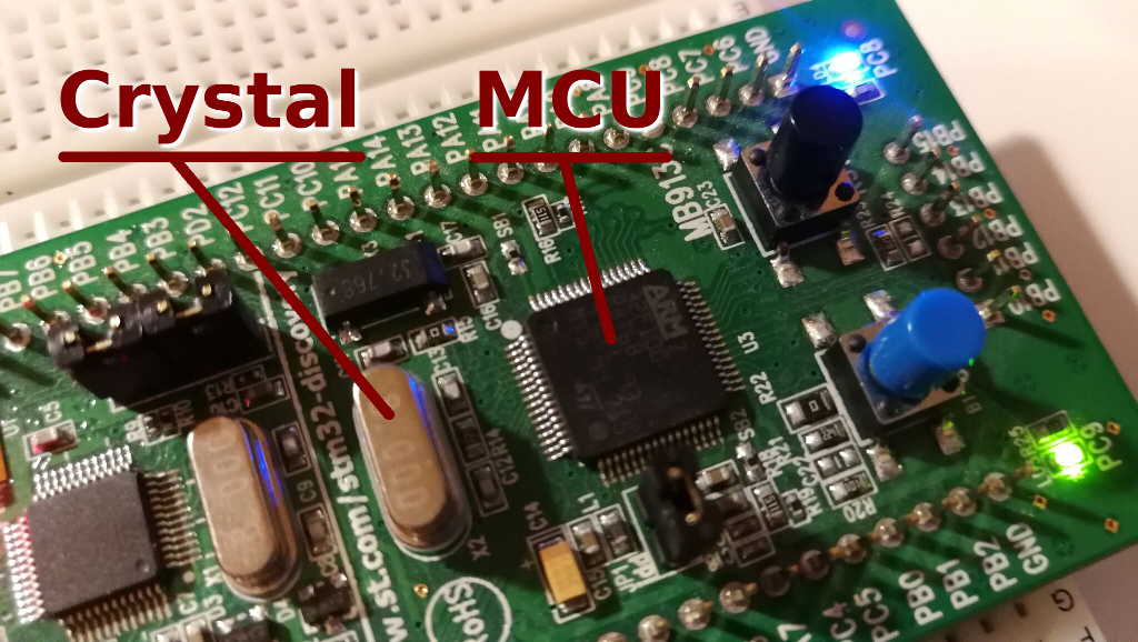
So, I have this STM32VLDISCOVERY dev board. It has the STM32F100RBT6B MCU, capable of running at 24MHz.
On the board, there is a 8MHz crystal.
Naturally, when you are new to microcontrollers (like me), you may have a few questions:
- When we upload a program on this development board, at what speed it is actually running?
- Is it using this external crystal?
- Why is this crystal 8MHz if the MCU is capable of 24MHz?
- If our program is not running at the maximum speed, how do we make it run at the maximum speed?
Let’s begin!
The Reference Manual
The reference manual (can be found here, direct link) has all the answers, but it is a beast. We deal with it using the following approach:
-
First, we realize that it is impossible to remember everything.
-
Therefore, we take notes.
-
We focus on the problem we want to solve.
-
We scan the document for things that are related to our problem, and write down interesting bits, together with the pages in the manual.
Especially important are the cryptic identifiers that may not make immediate sense, but then they will make sense together with all related information.
The Clock Problem
Turns out, the clocks are not so hard, but there is a lot of information (as always).
There are 3 ways (reference manual, 6.2) to drive system clock (SYSCLK):
-
HSI, internal high-speed oscillator clock. The chip itself has an oscillator inside which can generate a clock signal, with no help from an external crystal. Neat, huh. Turns out the internal resonator tends to be imprecise.
-
HSE, external high-speed oscillator clock. This is the crystal we are interested in.
-
PLL, the Phase Locked Loop, which can be the source for SYSCLK and can multiply either HSE or HSI by some number. That’s how we would get 24MHz from 8MHz!
Then, there are secondary clock sources, that can power some internal devices:
-
LSI, internal low-speed oscillator drives auto-wakeup and can drive RTC (real time clock).
-
LSE, external low-speed (32.768 kHz) crystal, can drive RTC with great precision.
At this moment we are mostly interested in the high-speed clock source, because it drives the SYSCLK and all the peripherals. The RTC also can be driven from HSE, and it actually increases its precision.
The figure 8 in the datasheet makes it all a bit easier to comprehend:
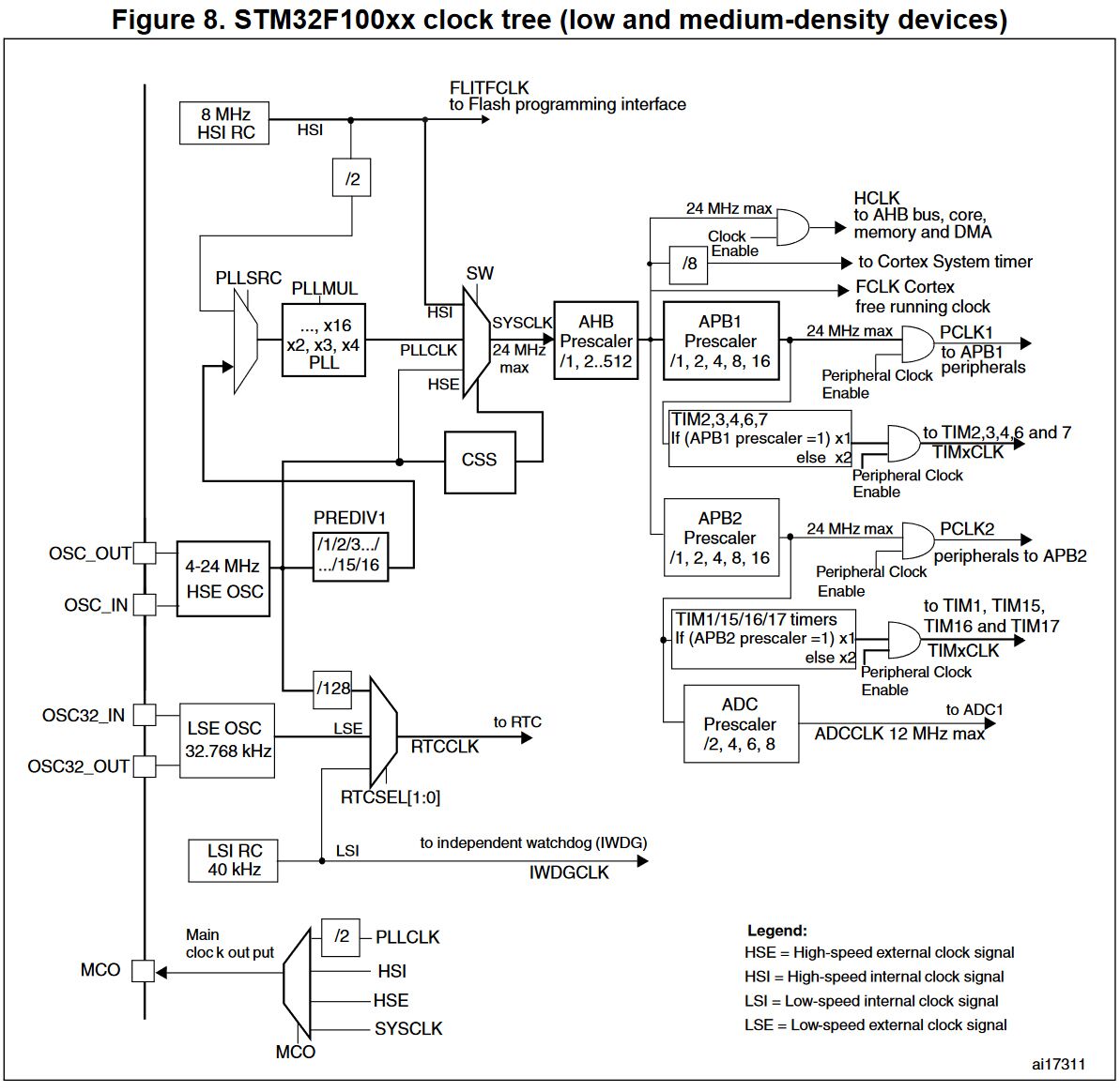
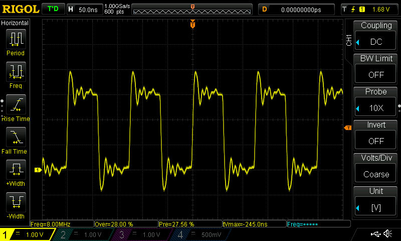
Here, we can plot the path from the external crystal to SYSCLK:
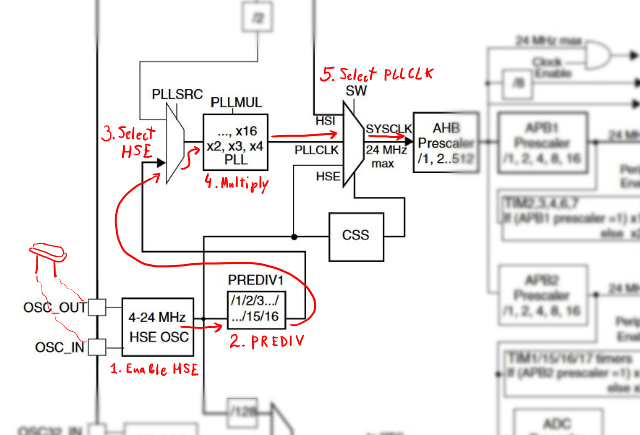
We need to:
- Enable HSE.
- Figure out what is this PREDIV1 and set it up.
- Select HSE in PLLSRC.
- Multiply clock frequency in PLLMUL and enable PLL.
- Select PLLCLK as SYSCLK source.
But first, what is the speed of the current clock?
Turns out, the MCU also has a master clock-out capability (reference manual, 6.2.10). The clock output is called MCO, and, as the document says:
The configuration registers of the corresponding GPIO port must be programmed in alternate function mode
The MCO can output either SYSCLK, HSI, HSE or PLL clock divided by 2 over
“corresponding GPIO port”.
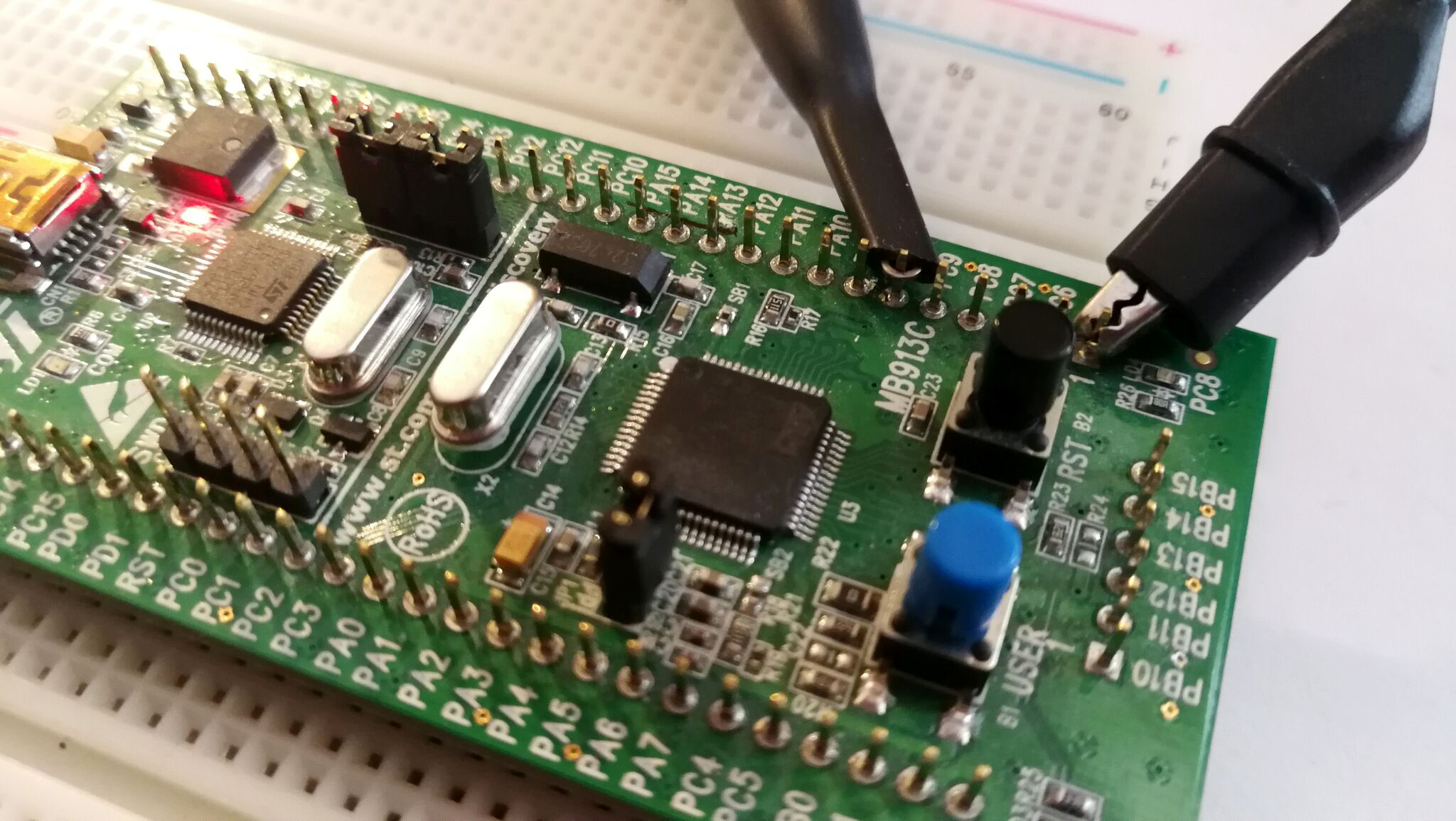
So, if we happen to have an oscilloscope, we can output it to a pin, and then measure this pin.
So, what is this “corresponding GPIO port”? To find out, we need the device datasheet.
From the STM32VLDISCOVERY description, we can find that it uses STM32F100RBT6B MCU. A quick search in octopart returns the exact properties of this part - it uses 64-pin LQFP package (of course, we could have counted the pins and measured the package, but this method was way faster).
From the part/device datasheet, we can find out the pinout of this exact package:
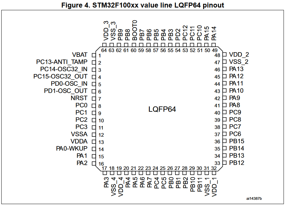
Bellow, Table 4 lists all device pins, their main functions (usually digital input and output), as well as alternate functions.
We should locate a pin that has MCO as the alternate function.
It is PA8:
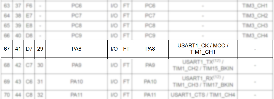
It turns out locating the exact device package was not necessary, because our STM32VLDISCOVERY lists the names of all ports. Still, it may prove useful later.
Now we know which port should be measured for the MCO output:
Back in the reference manual, we can find that register that enables MCO is
RCC_CFGR (reference manual, 6.3.2).
In the main function, we can start by taking peripherals, and then
enable SYSCLK selection for MCO:
(src/main.rs, in main function)
let peripherals = stm32f1::stm32f100::Peripherals::take().unwrap();
let rcc = peripherals.RCC;

// enable MCO alternate function (PA8)
rcc.cfgr.modify(|_r, w| w.mco().sysclk());

// continue here

loop {}
This has no effect, because we also need to enable the alternate function for this
pin. Table 27 (reference manual, 7.1.11) says that MCO alternate function should be
“Alternate function push-pull”.
We need to change GPIO MODE to output, and CNF pin to select this alternate function (GPIOx_CRH, reference manual, 7.2.2):
(src/main.rs, continued)
let port_a = peripherals.GPIOA;

// enable port clock
rcc.apb2enr.modify(|_r, w| w.iopaen().bit(true));
// configure port mode and enable alternate function
port_a.crh.modify(|_r, w| unsafe {
    w
        .mode8().bits(MODE_OUTPUT_50MHz)
        .cnf8().bits(CNF_AF_OUTPUT_PUSHPULL)
});
The growing list of defined constants:
(src/main.rs, outside main function)
const MODE_INPUT: u8 = 0b00;
const MODE_OUTPUT_10MHz: u8 = 0b01;
const MODE_OUTPUT_2MHz: u8 = 0b10;
const MODE_OUTPUT_50MHz: u8 = 0b11;

const CNF_OUTPUT_PUSHPULL: u8 = 0b00;
const CNF_INPUT_FLOATING: u8 = 0b01;
const CNF_AF_OUTPUT_PUSHPULL: u8 = 0b10;
To clean things up a bit, we can move MCO configuration into another function:
(src/main.rs, modified)
#[entry]
fn main() -> ! {
    let peripherals = stm32f1::stm32f100::Peripherals::take().unwrap();
    let mut rcc = peripherals.RCC;
    let mut port_a = peripherals.GPIOA;

    configure_mco(&mut rcc, &mut port_a);

    loop {

    }
}

fn configure_mco(rcc: &mut stm32f1::stm32f100::RCC, port: &mut stm32f1::stm32f100::GPIOA) {
    // enable port clock
    rcc.apb2enr.modify(|_r, w| w.iopaen().set_bit());
    // configure port mode and enable alternate function
    port.crh.modify(|_r, w| unsafe {
        w
            .mode8().bits(MODE_OUTPUT_50MHz)
            .cnf8().bits(CNF_AF_OUTPUT_PUSHPULL)
    });
    // enable MCO alternate function (PA8)
    rcc.cfgr.modify(|_r, w| w.mco().sysclk());
}
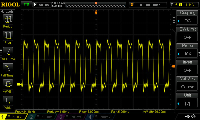
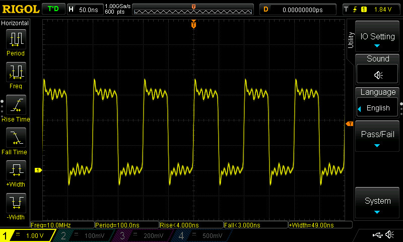
Here we go, our system clock is at 8MHz:
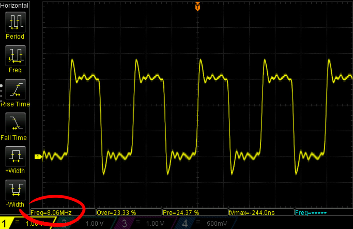
(the not-so-square clock signal is likely due to the breadboard capacitance and the probe wires)
Now that we can measure it, let’s continue working on enabling external oscillator (HSE).
STM32 Cube MX
Again, to configure the clock, we need to:
- Enable HSE.
- Set up PREDIV1.
- Select HSE in PLLSRC.
- Multiply clock frequency in PLLMUL and enable PLL.
- Select PLLCLK as SYSCLK source.
We got all this information from the datasheet. However, there is another way.
In the ideal world, we would have some fancy tool with graphical UI which would let us pick all those values for dividers and multipliers, and which would auto-generate the code required to do the same.
Enter the STM32 Cube MX, which aims to do exactly that. The generated code is in C. Still, it serves as a useful reference and a place to try things out, as we will see shortly.
Here we will attempt to create a new project with Cube MX, compile a part of it into a static library, and then include and use this static library in our project to initialize the clock.
If you want to jump ahead into the pure-rust implementation, skip this section.
In the “New Project” window of tool, we can find the exact chip we are using.
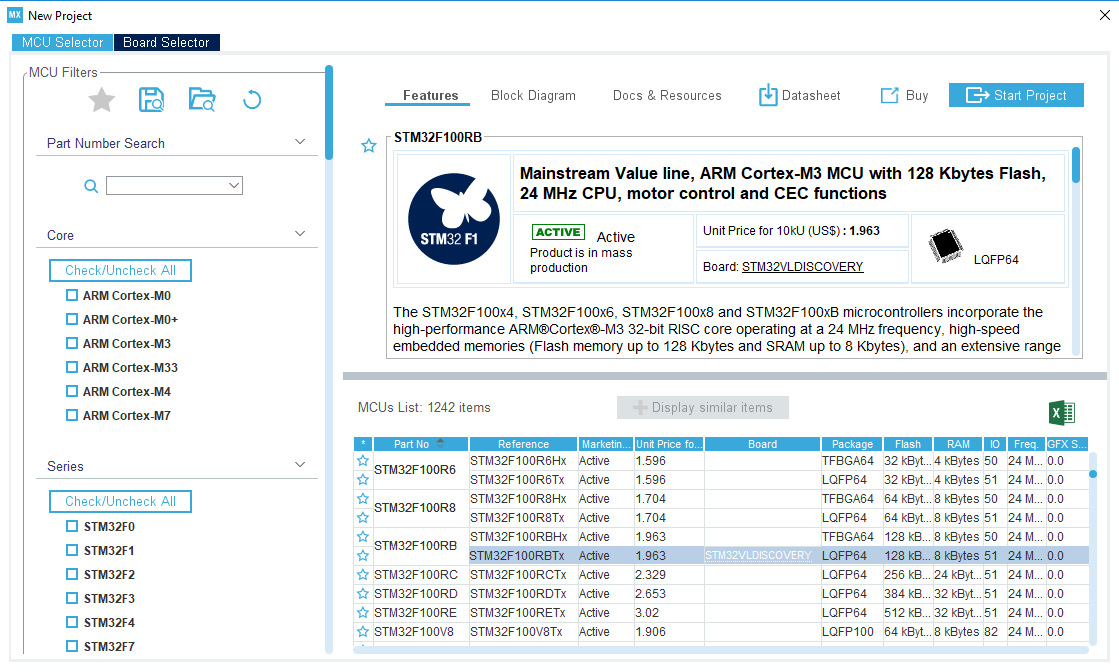
And then click “Start Project”.
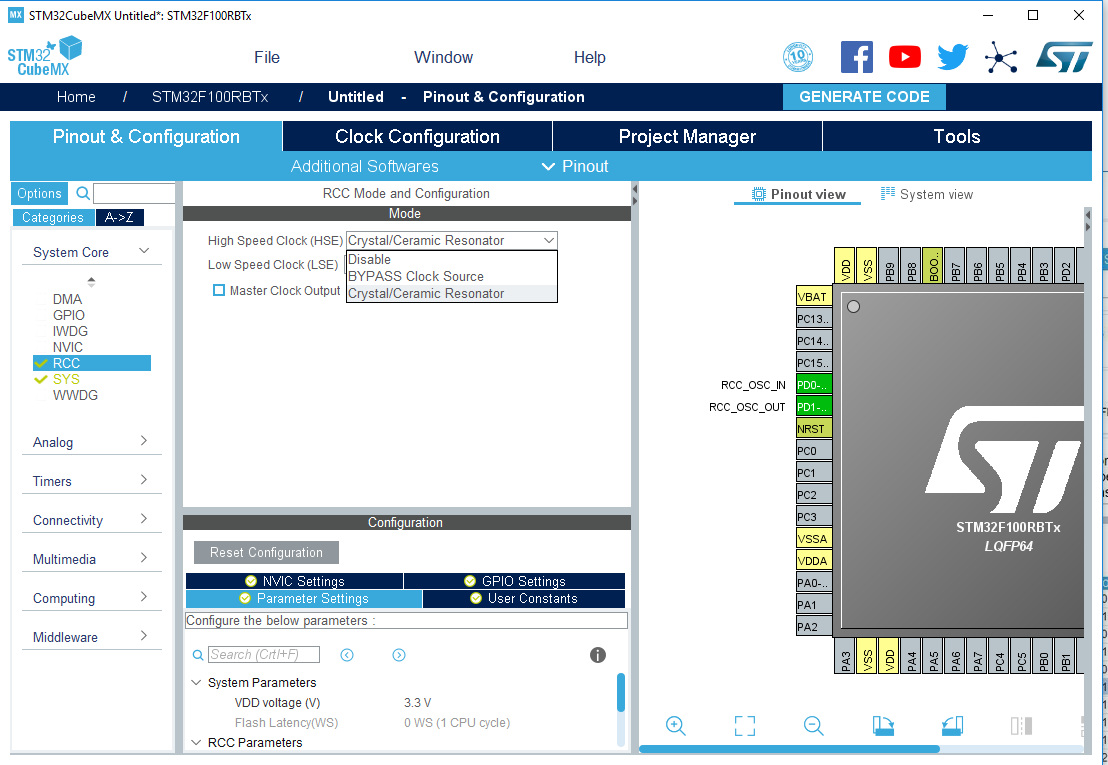
In the “Pinout & Configuration” tab -> “System Core” -> “RCC” menu we can pick “Crystal/Ceramic Resonator” for HSE.
Now, the UI in “Clock Configuration” tab allows us to select HSE as PLL input:
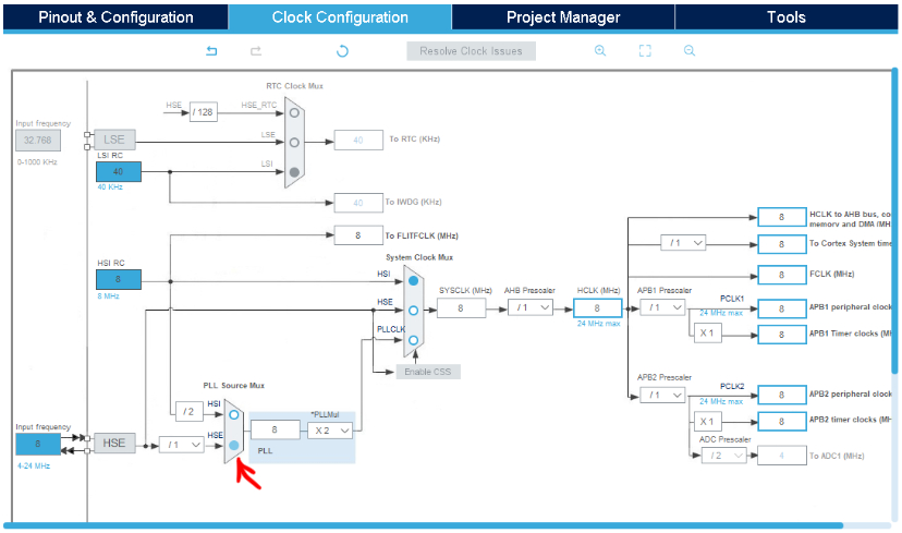
(We leave PREDIV set to /1)
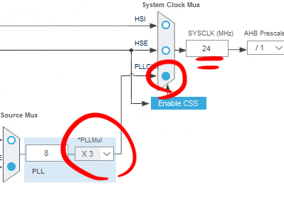
Then we select PLL multiplier X3 and pick PLL as input for SYSCLK to get 24MHz system clock:
Compiling C from Rust
We are going to use C files directly from the generated project in our crate.
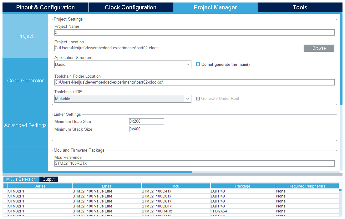
Therefore, I have named the project c and exported it to our crate directory:
The function that configures the clock is in exported c/Src/main.c, and is
named SystemClock_Config.
There is also the main function nearby. I have renamed it to no_main to prevent
the linker from picking it up as the entry point.
As we can see from main, the first thing it does is call HAL_Init. Unfortunately,
this also initializes SysTick, which will fire SysTick interrupt. As we can find
from c/Src/stm32f1xx_it.c handler implementation, this interrupt calls HAL_IncTick
function.
However, we want to keep using cortex-m interrupt implementation from the rust crate
we have already included. However, we should be able
to link and call the same HAL_IncTick interrupt handler from Rust.
If we dig around in HAL code, we can find out that SysTick is used for timeout
when waiting for clocks to start up. So this HAL_Init is definitely required
by SystemClock_Config function if we want to keep the existing C code as-is.
To put it all together, we can start by compiling main.c file and everything else
it needs. We will do this from the cargo build script.
Let’s add cc build-time dependency in Cargo.toml:
(Cargo.toml)
[build-dependencies]
cc = "1.0.28"
And then add additional code in build.rs main function to compile bunch of related
c files into archive:
    cc::Build::new()
        .define("USE_HAL_DRIVER", None) // found in makefile
        .define("STM32F100xB", None) // found in makefile
        .include("c/Inc")
        .include("c/Drivers/CMSIS/Include")
        .include("c/Drivers/CMSIS/Device/ST/STM32F1xx/Include")
        .include("c/Drivers/STM32F1xx_HAL_Driver/Inc")
        .file("c/Src/main.c")
        .file("c/Src/system_stm32f1xx.c")
        .file("c/Drivers/STM32F1xx_HAL_Driver/Src/stm32f1xx_hal.c")
        .file("c/Drivers/STM32F1xx_HAL_Driver/Src/stm32f1xx_hal_cortex.c")
        .file("c/Drivers/STM32F1xx_HAL_Driver/Src/stm32f1xx_hal_gpio.c")
        .file("c/Drivers/STM32F1xx_HAL_Driver/Src/stm32f1xx_hal_rcc.c")
        .flag("-fno-pic") // useful to force ar to resolve all symbols
        .archiver("arm-none-eabi-ar") // no archiver in env variable, specify manually
        .compile("libdevice.a"); // this will get picked by rust crate automatically

    // run this script again when we change main.c
    println!("cargo:rerun-if-changed=c/Src/main.c");
How I came up with this? Well, I have started from .file("c/Src/main.c") and
kept fixing errors until it worked.
With this done, all we need to do is tell Rust about the existance of C functions we are going to use:
(src/main.rs, added)
extern "C" {
    fn HAL_Init();
    fn HAL_IncTick();
    fn SystemClock_Config();
}
We can call them at the start of main:
(src/main.rs, added lines at the start of main function)
#[entry]
fn main() -> ! {

    unsafe { HAL_Init(); }
    unsafe { SystemClock_Config(); }

    ...
}
When we run it like this, the GDB hits the DefaultHandler_ breakpoint. We can
get rid of it by implementing SysTick exception and forwarding SysTick to HAL:
(src/main.rs, added “exception” to “use” statement)
use cortex_m_rt::{entry, exception};
(src/main.rs, added SysTick handler)
#[exception]
fn SysTick() {
    unsafe { HAL_IncTick() }
}
Well, surprisingly, it works. We have a chip running system clock at the maximum speed:
However, the final result leaves a lot to be desired: the peripheral initialization code is in Rust (MCO), while rcc initialization is in C (HSE-PLL-SYSCLK). The HAL on C side has some hidden state (for example, if we update clock speed on Rust side we need to call HAL function to update the configuration). HAL is also using this SysTick exception that runs updates from the Rust side. It all looks a bit messy.
However, I can imagine someone picking a hybrid approach where all high-level code is written in Rust and calls back to HAL C code, which already has a lot of stuff implemented.
Likewise, a hybrid approach where things are configured on Rust side also looks feasible, with maybe occasional driver implemented in C.
So, how would the pure-Rust configuration look like?
Configuring clocks from scratch, in Rust
And yet again:
- Enable HSE.
- Set up PREDIV1.
- Select HSE in PLLSRC.
- Multiply clock frequency in PLLMUL and enable PLL.
- Select PLLCLK as SYSCLK source.
First, we need to enable HSE:
Now, we have two sources of information: the reference manual and the auto-generated C code.
Let’s also remove or comment out all the C code invocations we added previously.
From the reference manual (6.3.1): enable HSE (HSEON flag) and then wait until it is ready (HSERDY).
(src/main.rs, continued)
// enable HSE
rcc.cr.modify(|_r, w| w.hseon().set_bit());

// wait for HSE to become ready

let mut ready = false;
while !ready {
    if rcc.cr.read().hserdy().bit_is_clear() {
        hprintln!("Not ready");
    } else {
        ready = true;
    }
}

hprintln!("Ready");
We receive this output in OpenOCD console:
Not ready
Ready
As the manual says, it takes at least 6 cycles for clock to become ready.
These print statements are temporary of course, and can be replaced with a simple loop:
(src/main.rs, modified)
// enable HSE
rcc.cr.modify(|_r, w| w.hseon().set_bit());

// wait for HSE to become ready
while rcc.cr.read().hserdy().bit_is_clear() {}
And we can organize things a bit and move all this clock initialization into another function:
(src/main.rs, modified main, added function configure_system_clock)
#[entry]
fn main() -> ! {
    let peripherals = stm32f1::stm32f100::Peripherals::take().unwrap();
    let mut rcc = peripherals.RCC;
    let mut port_a = peripherals.GPIOA;

    configure_mco(&mut rcc, &mut port_a);
    configure_system_clock(&mut rcc);

    loop {

    }
}

fn configure_mco(rcc: &mut stm32f1::stm32f100::RCC, port: &mut stm32f1::stm32f100::GPIOA) {
    // enable port clock
    rcc.apb2enr.modify(|_r, w| w.iopaen().set_bit());
    // configure port mode and enable alternate function
    port.crh.modify(|_r, w| unsafe {
        w
            .mode8().bits(MODE_OUTPUT_50MHz)
            .cnf8().bits(CNF_AF_OUTPUT_PUSHPULL)
    });
    // enable MCO alternate function (PA8)
    rcc.cfgr.modify(|_r, w| w.mco().pll());
}

fn configure_system_clock(rcc: &mut stm32f1::stm32f100::RCC) {
    rcc.cr.modify(|_r, w| w.hseon().set_bit());
    while rcc.cr.read().hserdy().bit_is_clear() {}

    // continue here
}
We can temporarily modify MCO output to output the HSE clock:
(src/main.rs, modification in configure_mco function)
// enable MCO alternate function (PA8)
rcc.cfgr.modify(|_r, w| w.mco().hse());
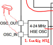
The scope outputs very stable 8MHz clock that does not jump around like internal RC clock did.
The HSE 8MHz speed matches crystal speed, which makes complete sense.
2, 3 and 4. Configuring PLL
- Enable HSE.
- Set up PREDIV1.
- Select HSE in PLLSRC.
- Multiply clock frequency in PLLMUL and enable PLL.
- Select PLLCLK as SYSCLK source.
Instead of HSE, let’s output PLL over MCO:
(src/main.rs, modification in configure_mco function)
// enable MCO alternate function (PA8)
rcc.cfgr.modify(|_r, w| w.mco().pll());
Then, let’s configure PREDIV1 division factor (reference manual, 6.3.11) to some value we may clearly notice. Let’s divide the clock by 4:
(src/main.rs, continued)
// PREDIV1 PLL input divider (from reference manual)
const RCC_CFGR2_DIV2: u8 = 0b0011; // bits = divider - 1 (3 = 4 - 1)
rcc.cfgr2.modify(|_r, w| unsafe { w.prediv1().bits(RCC_CFGR2_DIV4)});

// continue here
Then, select PREDIV1 as PLLSRC (reference manual, 6.3.2).
(src/main.rs, continued)
// select PREDIV1 as PLLSRC
rcc.cfgr.modify(|_r, w| w.pllsrc().hse_div_prediv());

// continue here
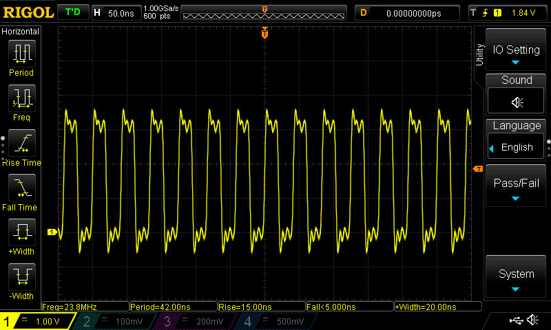
To see the PLL with scope, we have to enable it. However, the manual says (6.2.3) that PLL output must be between 16-24MHz. And we don’t want to upset the manual, so before enabling PLL, we also multiply the value by 10.
So, 8MHz clock was divided by 4, then multiplied by 10, that should give us 20MHz PLL:
(src/main.rs, continued)
// configure pll multiplier
rcc.cfgr.modify(|_r, w| w.pllmul().mul10());
// turn pll on
rcc.cr.modify(|_r, w| w.pllon().set_bit());
// wait for pll to become ready
while rcc.cr.read().pllrdy().bit_is_clear() {}

// continue here
Let’s see:
Huh. We get 10MHz, and that is completely correct. As the manual says (6.2.10), if we send PLL to MCO, it will get divided by 2. So it works.
5. PLL as the System Clock source
- Enable HSE.
- Set up PREDIV1.
- Select HSE in PLLSRC.
- Multiply clock frequency in PLLMUL and enable PLL.
- Select PLLCLK as SYSCLK source.
To achieve target PLL speed of 24MHz, we can PREDIV 8MHz by 2 and then multiply 4MHz output by 6:
(src/main.rs, modified configure_system_clock function)
fn configure_system_clock(rcc: &mut stm32f1::stm32f100::RCC) {
    rcc.cr.modify(|_r, w| w.hseon().set_bit());
    while rcc.cr.read().hserdy().bit_is_clear() {}

    const RCC_CFGR2_DIV2: u8 = 0b0001; // bits = divider - 1 (1 = 2 - 1)
    rcc.cfgr2.modify(|_r, w| unsafe { w.prediv1().bits(RCC_CFGR2_DIV2)}); // changed to div2
    rcc.cfgr.modify(|_r, w| w.pllsrc().hse_div_prediv());

    rcc.cfgr.modify(|_r, w| w.pllmul().mul6()); // set to mul 6
    rcc.cr.modify(|_r, w| w.pllon().set_bit());
    while rcc.cr.read().pllrdy().bit_is_clear() {}

    // continue here
}
Then, we can set PLL as system clock input (reference manual, 6.3.2):
(src/main.rs, continued)
    rcc.cfgr.modify(|_r, w| w.sw().pll());
    while !rcc.cfgr.read().sws().is_pll() {}
Let’s not forget to set MCO back to SYSCLK:
(src/main.rs, modification in configure_mco function)
    // enable MCO alternate function (PA8)
    rcc.cfgr.modify(|_r, w| w.mco().sysclk());
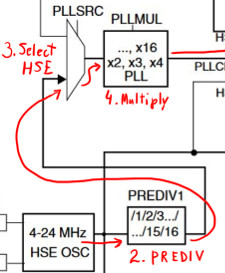
Here we go:
Summary
This was a great learning experience! We learned how to get around the reference manual, got familiar with Rust STM32 device API, got familiar with official CubeMX tool, compiled and used auto-generated C code from Rust, as well as written all code we needed in pure Rust.
What is missing still: our Rust code is going to hang if the clocks fail to start, while the C HAL implementation uses timeouts. We will leave this problem for later.
Source code
Source code can be found here.