Embedded Rust Experiments - Flipping some bits high on STM32VLDISCOVERY board
Here I will document the steps to get started with STM32VLDISCOVERY board.
We will take my favourite “from scratch” approach. That way, we build the final thing step by step while building our understanding of how it all fits together.
I am new to Cortex-M, and I am new to Rust’s embedded development, so please excuse me if I get some terminology horribly wrong. I am also learning along the way, and then I try to present what I have learned in a sequential, easy to understand way.
Documentation
Go to ST site and locate the board documentation.
Board uses STM32F100RBT6B Cortex-M3 microcontroller (MCU). Locate the documentation of this MCU too. The page has many PDFs. We are interested in what is called the “reference manual”. It’s big (direct link.
The final code is available on the github.
Connection to the board
The board contains the MCU and everything that is required to run it, as well as a programmer called ST-Link.
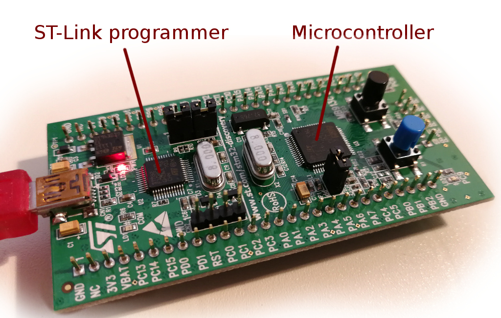
By default it is configured to program the MCU on the board. However, we can change some jumpers, connect 4 wires to pins marked “SWD” and use ST-Link to program similar MCU on another board designed by us (however it is likely we won’t do this, because we will get distracted by more recent shiny MCUs). This board is good for testing this MCU, because all the pins are accessible and plugable to a breadboard.
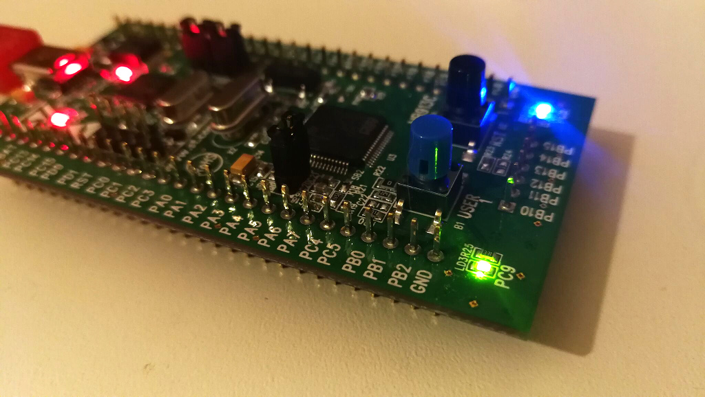
Here it is, plugged into two breadboards, and powering it with 3.3V from GND and
3V3 pins. As you can see, it lights up an external LED.
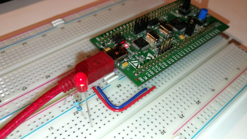
The designers of this board clearly did not design it to be used this way: especially annoying is the parallel row of pins at the end of the board.
We connect to ST-Link over an USB cable.
USB and ST-Link
We will make sure that we have a connection to our board by installing OpenOCD (which will be used to upload our program to MCU).
Make sure your rust version is at least 1.31
Here we can find the set up instructions for OpenOCD (and other tools):
Follow them and install tools for our platform.
For Windows, you can download the driver from the board page we’ve visited before.
Then, follow the instructions to verify that you have connection to the board with one
caveat: change openocd call to use different device than the book says. Our
device in our board is STM32F100RB. We can browse installed OpenOCD scripts
to locate the board cfg file and use it as -f command line option.
With OpenOCD 0.10, this works for me:
openocd -f interface/stlink-v2-1.cfg -f target/stm32f1x.cfg
It is likely that you will receive this error on Windows:
...
Error: libusb_open() failed with LIBUSB_ERROR_NOT_SUPPORTED
Windows has multiple mechanisms to load drivers. OpenOCD uses WinUSB. I had to use Zadig tool to install WinUSB version of STM32 STLink driver. Follow the instructions here, except our driver should be named “STM32 STLink”.
If the LED starts blinking, the connection is successful! You should leave the OpenOCD running in another terminal window.
Back to Rust
We will need Rust 1.31 (stable).
$ rustc -V
rustc 1.31.1 (b6c32da9b 2018-12-18)
We will bootstrap a Rust project from scratch.
First, let’s create a simple Rust project:
cargo new --bin blink
cd blink
This generates the familiar “Hello, world!” project for us:
(src/main.rs)
fn main() {
    println!("Hello, world!");
}
Here we are not using Rust 2018, so remove
edition = "2018"from Cargo/toml file.
No std
MCUs have small, constrained environments. Convenient things like heap require more work or are not used at all. We start by disabling Rust’s standard library:
(at the top of main.rs)
#![no_std]
And guess what, the println! macro no longer exists:
error: cannot find macro `println!` in this scope
So we remove it:
(main.rs, full)
#![no_std]

fn main() {
}
We get another error when compiling:
error: language item required, but not found: `eh_personality`
The eh_personality is used to implement stack unwinding in case a panic occurs.
But this is very dependent on the platform we are compiling to; right up to this point we
attempted to compile no_std executable for windows/linux/mac; it’s time we switch our target architecture
to the one required by our MCU.
ARM target
Our board has Cortex-M3 MCU, and the rust “target” name for it is thumbv7m-none-eabi.
This identifier is the best-effort combination of names that describe instruction set (thumbv7m),
operating system (none) and executable format (ELF ABI). It does not have “hf” suffix at the end
because our MCU does not support hardware floating point operations.
If we used another Cortex-M MCU, we would choose another target triple:
thumbv6m-none-eabi, for the Cortex-M0 and Cortex-M1 processorsthumbv7m-none-eabi, for the Cortex-M3 processorthumbv7em-none-eabi, for the Cortex-M4 and Cortex-M7 processorsthumbv7em-none-eabihf, for the Cortex-M4F and Cortex-M7F processors
Rustup can download core library for our target:
rustup target add thumbv7m-none-eabi
From now on, when we compile our program, we use --target thumbv7m-none-eabi flag:
cargo build --target thumbv7m-none-eabi
When we try to compile it now, we see that eh_personality error disappeared, and
instead we get:
error: `#[panic_handler]` function required, but not found
With #![no_std] flag the standard library got removed, and now nothing implements
the panic handler. There is a crate though that simply halts the program on panic,
panic-halt:
(Cargo.toml)
[dependencies]
panic-halt = "0.2.0"
(src/main.rs)
extern crate panic_halt;
Now, the panic_handler error is gone, but we got the next one:
error: requires `start` lang_item
Cortex-M Runtime
Turns out that the main function is not the first thing that is called when the program starts.
On Windows, the entry function is mainCRTStartup, which initializes some things and
only then it calls the main.
There is also a similar story when we build executable for our MCU:
something on the MCU has to invoke our main function, like when we press the reset
button, or when the MCU boots up. And the Rust can’t know
about it, therefore it tells us to define our own start function, which can then
call the familiar main.
There is a library we can link into our program that provides a minimal runtime for
Cortex-M microcontrollers: it has a reset handler which calls our main, and also
defines the start lang item.
Let’s add it to Cargo.toml dependencies:
(Cargo.toml)
[dependencies]
cortex-m-rt = "0.6.7"
Now we can read the documentation for cortex-m-rt to find out exactly how to write our main function:
(src/main.rs, whole file)
#![no_std]
#![no_main]

extern crate panic_halt;
extern crate cortex_m_rt;

use cortex_m_rt::entry;

// use `main` as the entry point of this application
// `main` is not allowed to return
#[entry]
fn main() -> ! {
    // initialization

    loop {
        // application logic
    }
}
Let’s build it:
cargo rustc --target thumbv7m-none-eabi -- \
            -C linker=arm-none-eabi-ld -C link-arg=-nostartfiles -C link-arg=-Tlink.x
note: C:\Program Files (x86)\GNU Tools ARM Embedded\7 2017-q4-major\bin\arm-none-eabi-ld.exe:
    cannot open linker script file memory.x: No such file or directory
When linking the executable, the linker picks up information about our MCU from
file memory.x, which describes certain memory locations on our MCU. Different MCUs will
have different values there, so ideally we would need to figure them out from the datasheet.
But if you are using the same board, go ahead and create the same file:
(memory.x)
MEMORY
{
  /* NOTE K = KiBi = 1024 bytes */
  /* Adjust these memory regions to match your device memory layout */
  FLASH : ORIGIN = 0x08000000, LENGTH = 128K
  RAM : ORIGIN = 0x20000000, LENGTH = 8K
}

_stack_start = ORIGIN(RAM) + LENGTH(RAM);
The linker is able to find it in the root project directory. However, in my project I have a workspace, with crates designed to work with different chips.
So I will add a build file that will explicitly pick memory.x from the crate
directory instead of the workspace root:
(build.rs, added)
use std::env;
use std::fs::File;
use std::io::Write;
use std::path::PathBuf;

fn main() {
    // Put the linker script somewhere the linker can find it
    let out = &PathBuf::from(env::var_os("OUT_DIR").unwrap());
    File::create(out.join("memory.x"))
        .unwrap()
        .write_all(include_bytes!("memory.x"))
        .unwrap();
    println!("cargo:rustc-link-search={}", out.display());

    // Only re-run the build script when memory.x is changed,
    // instead of when any part of the source code changes.
    println!("cargo:rerun-if-changed=memory.x");
}
Finally, we should be able to build it!
cargo rustc --target thumbv7m-none-eabi -- \
            -C linker=arm-none-eabi-ld -C link-arg=-Tlink.x
Finished dev [unoptimized + debuginfo] target(s) in 0.18s
.cargo/config file
It is more convenient to put these -C configuration bits into
.cargo/config file. That way cargo will pick these flags automatically when
building the appropriate architecture.
Let’s create .cargo/config for our project. It follows toml file format, but does
not have .toml extension:
(.cargo/config)
[build]
# Pick ONE of these compilation targets
# target = "thumbv6m-none-eabi"    # Cortex-M0 and Cortex-M0+
target = "thumbv7m-none-eabi"    # Cortex-M3
# target = "thumbv7em-none-eabi"   # Cortex-M4 and Cortex-M7 (no FPU)
# target = "thumbv7em-none-eabihf" # Cortex-M4F and Cortex-M7F (with FPU)
This eliminates the need of --target thumbv7m-none-eabi parameter. It is now the default,
and this should work the same as before:
cargo rustc -- -C linker=arm-none-eabi-ld -C link-arg=-Tlink.x
Then we can put other -C options in config file too:
(.cargo/config, whole file)
[build]
# Pick ONE of these compilation targets
# target = "thumbv6m-none-eabi"    # Cortex-M0 and Cortex-M0+
target = "thumbv7m-none-eabi"    # Cortex-M3
# target = "thumbv7em-none-eabi"   # Cortex-M4 and Cortex-M7 (no FPU)
# target = "thumbv7em-none-eabihf" # Cortex-M4F and Cortex-M7F (with FPU)


rustflags = [
  # LLD (shipped with the Rust toolchain) is used as the default linker
  "-C", "link-arg=-Tlink.x",

  # if you run into problems with LLD switch to the GNU linker by commenting out
  # this line
  "-C", "linker=arm-none-eabi-ld",

  # if you need to link to pre-compiled C libraries provided by a C toolchain
  # use GCC as the linker by commenting out both lines above and then
  # uncommenting the three lines below
  # "-C", "linker=arm-none-eabi-gcc",
  # "-C", "link-arg=-Wl,-Tlink.x",
  # "-C", "link-arg=-nostartfiles",
]
Now we can build our project with simple cargo build.
Running
Similarly, we can configure cargo run to load our binary in the MCU
and start executing it.
Let’s expand .cargo/config with these options:
(.cargo/config, add at the end)
[target.'cfg(all(target_arch = "arm", target_os = "none"))']
# uncomment ONE of these three option to make `cargo run` start a GDB session
# which option to pick depends on your system
#runner = "arm-none-eabi-gdb -q -x openocd.gdb"
runner = "arm-none-eabi-gdb -q -x openocd_run.gdb"
# runner = "gdb-multiarch -q -x openocd.gdb"
# runner = "gdb -q -x openocd.gdb"
Then, let’s create openocd_run.gdb file and write gdb commands into it:
(openocd_run.gdb)
target extended-remote :3333

# print demangled symbols
set print asm-demangle on

# detect unhandled exceptions, hard faults and panics
break DefaultHandler
break UserHardFault
break rust_begin_unwind

monitor arm semihosting enable
load
continue
We also need a openocd.cfg file:
(openocd.cfg)
source [find interface/stlink-v2-1.cfg]
source [find target/stm32f1x.cfg]
Here we use the correct STLink interface script and the device configuration.
To continue, the OpenOCD must be running in the background and the red led on the MCU dev board should be blinking.
cargo run
Running `arm-none-eabi-gdb -q -x openocd_run.gdb C:\Users\...\embedded-experiments\target\thumbv7m-none-eabi\debug\part01-blink`
...
semihosting is enabled
Loading section .vector_table, size 0x400 lma 0x8000000
Loading section .text, size 0x2f8 lma 0x8000400
Loading section .rodata, size 0xd0 lma 0x80006f8
Start address 0x8000404, load size 1992
Transfer rate: 6 KB/sec, 664 bytes/write.
Something has happened. It would be great if we could print a “Hello world” somehow. Luckily, the chip supports semihosting, and can send back signals with messages.
Let’s include cortex-m-semihosting crate in dependencies:
(Cargo.toml)
[dependencies]
cortex-m-semihosting = "0.3.2"
Then add a reference to the crate in main.rs:
(src/main.rs)
extern crate cortex_m_semihosting;
And pull hprintln macro from it:
(src/main.rs)
use cortex_m_semihosting::hprintln;
And then modify the main function:
(src/main.rs)
#[entry]
fn main() -> ! {
    // initialization

    hprintln!("Hello, world!").unwrap();

    loop {
        // application logic
    }
}
Let’s run it again:
cargo run
We should see:
Hello, world!
In OpenOCD terminal.
Semihosting abort
Instead of the panic_halt, which halts program on panic (and should probably be used
in production), we can use panic_semihosting crate when we have this semihosting link.
This way we will receive way more information about any panic in our program.
This is simple: we replace panic_halt crate with panic_semihosting.
(Cargo.toml)
[dependencies]
#panic-halt = "0.2.0"
panic-semihosting = "0.5.1"
And reference the appropriate crate:
(src/main.rs)
extern crate panic_semihosting;
//extern crate panic_halt;
The device crate
We can now control the device by reading and writing data to the correct memory locations.
Luckily, there is a stm32f1 device crate, that wraps it all in a nicer API.
(Cargo.toml)
[dependencies.stm32f1]
version = "0.6.0"
features = ["stm32f100", "rt"]
We select the device we want with stm32f100 feature flag (see the list of devices in crate
README), and we can also add rt feature, which brings
in cortex-m-rt we added previously.
We can remove cortex-m-rt crate now:
(Cargo.toml)
[dependencies]
# cortex-m-rt = "0.6.7"
We are now left with this main.rs:
#![no_std]
#![no_main]

extern crate stm32f1;
extern crate panic_semihosting;
//extern crate panic_halt;
extern crate cortex_m_rt;
extern crate cortex_m_semihosting;

use cortex_m_rt::entry;
use cortex_m_semihosting::hprintln;

// use `main` as the entry point of this application
// `main` is not allowed to return
#[entry]
fn main() -> ! {
    // initialization

    hprintln!("Hello, world!").unwrap();

    loop {
        // application logic
    }
}
This (Cargo.toml):
[package]
name = "part01-blink"
version = "0.1.0"

[dependencies]
#panic-halt = "0.2.0"
panic-semihosting = "0.5.1"
cortex-m-rt = "0.6.7"
cortex-m-semihosting = "0.3.2"

[dependencies.stm32f1]
version = "0.6.0"
features = ["stm32f100", "rt"]
memory.x file, openocd.cfg/openocd_run.gdb, .cargo/config files, and a decent grasp
of how this all fits together.
One small detail: to minimize the executable size, we should always compile with --release
flag. To optimize the usage of many crates, we should link with Link Time Optimization (LTO).
And we can also enable debugging in release mode. We can set this up in Cargo.toml
release profile:
(Cargo.toml, at the end)
[profile.release]
lto = true
debug = true
Lighting up the LEDs
In our case, we are interested in turning on the built-in LEDs on our board.
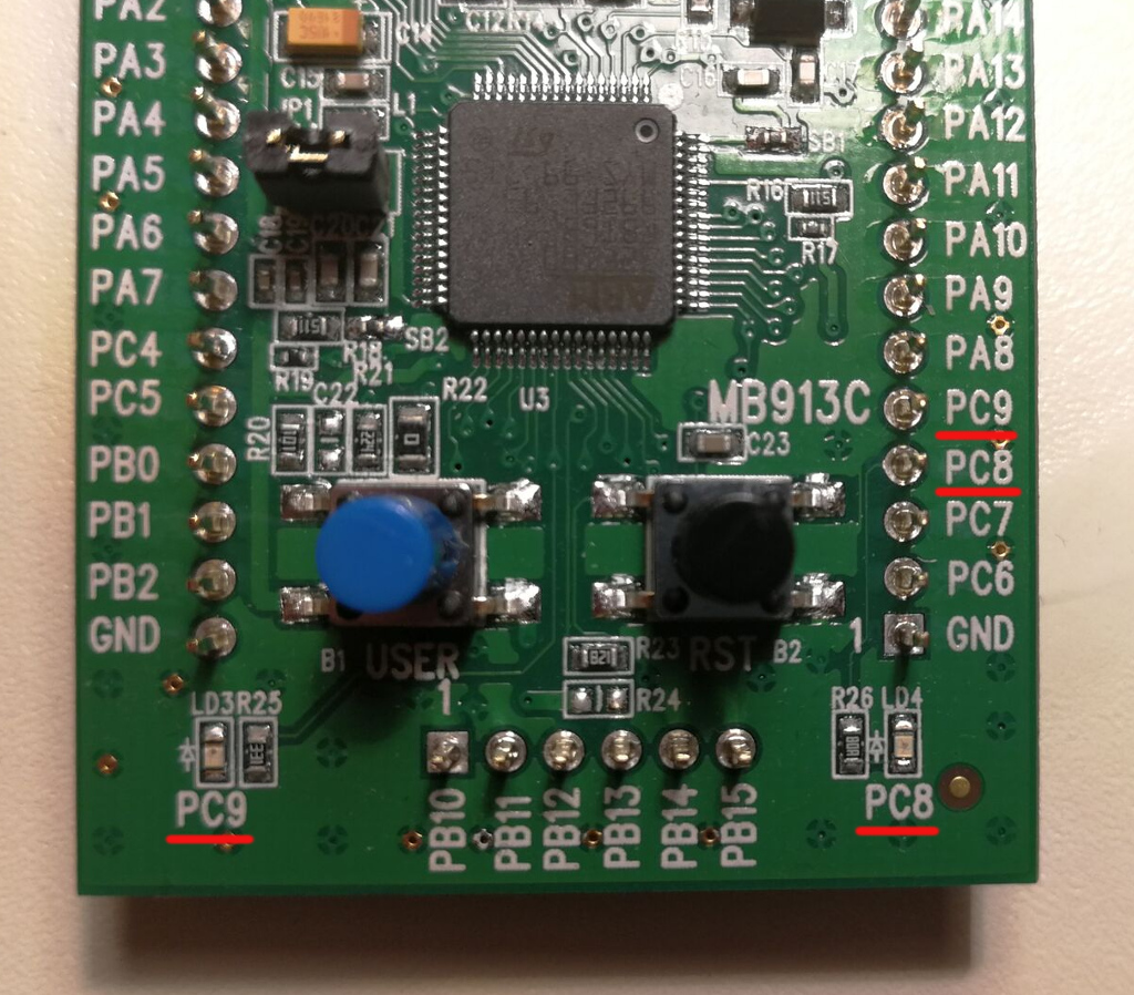
What do those PC8 and PC9 names mean?
Ports
MCU’s inputs and outputs are grouped into ports. Ports are named A, B, C and so on.
On this MCU, each port has 16 pins, that correspond to physical pins on the board.
They are named from 0 to 15. So, the pin 9 on port C would be named PC9.
Port I/O
Each pin can be individually configured to be either an input or an output.
Input
In input mode, pin is configured to sense the voltage applied to it. By default
the pin is configured to sense digital logic, that means that low voltage will
be read as 0, while the high voltage will be read as 1. Some pins can also
be configured to read analog voltage, by employing an internal Analog-Digital
Converter (ADC for short).
But what does the pin sense when there is nothing connected to it? Well, any ambient voltage around it! Think of it as a very undefined behavior. For that reason the inputs can be configured to be tied to high (pull-up) or low (pull-down) voltage over the high-value resistor. The pin can then read any value that is connected to this pin and does not have such a high resistance, effectively overriding the default pull-up or pull-down.
Output
An output in so-called push-pull configuration either sources high voltage when the
output is 1 or drains low voltage when the output is 0. Without heavy terminology,
you would read 1/0 if the output is 1/0.
Output pin can also have other configurations. For example, this MCU can configure pin
to actively drain current only when the output is 0, and do nothing (think - pin unconnected)
when the output is 1. Such configuration is called open-drain.
Voltage
What is called Low and High voltage?
Low
Low corresponds to digital value 0, and it is the so-called “ground” value. The pin
for it is named GND.
High
High voltage corresponds to 1 and is the voltage at which the MCU is operating.
In this case, MCU is working at 3.3V even though the USB cable supplies 5V.
There is a small voltage regulator chip on our board that supplies 3.3V voltage
to our MCU.
It is simply easier to talk about high and low than name the exact voltage values.
It is usually the case that some pins on MCU can read higher voltage (in our case it may
be 5V) than the MCU itself is operating on. That would still be “high” for a digital input
pin. If the pins can actually read higher voltage, well, it’s best to read the datasheet
to find out. Quick answer: yes, this MCU GPIO ports can do that,
but not in pull-up/pull-down mode (Section 5.3.13).
GPIO on our MCU
With this background information, we can start reading section 7.1 of the reference manual and take some notes.
We find that ports have registers:
GPIOx_CRL,GPIOx_CRHare configuration registers;GPIOx_IDR,GPIOx_ODRdata registers;GPIOx_BSRRset/reset register;GPIOx_BRRreset register;GPIOx_LCKRlocking register.
At this point it is unclear what exactly they all mean, but we should remember this terminology and continue reading.
The manual lists possible pin modes, which we can understand now:
- Input floating
- Input pull-up
- Input-pull-down
- Analog
- Output open-drain
- Output push-pull
- Alternate function push-pull
- Alternate function open-drain
We learn that there are some alternate configurations, which we probably won’t need.
We find this sentence:
Each I/O port bit is freely programmable,
however the I/O port registers have
to be accessed as 32-bit words
We know that we have added stm32f1 crate with an API to this device,
and we hope we can avoid thinking of exact/relative address locations or how the
registers have to be accessed. This simplifies the situation a bit.
The purpose of the GPIOx_BSRR and GPIOx_BRR
registers is to allow atomic read/modify
accesses to any of the GPIO registers.
We learn that GPIOx_BSRR and GPIOx_BRR can be used for modifying
pin values (looks relevant!) without data races (maybe Rust can help here?).
Then we have bunch of diagrams in Figure 11 and Figure 12, with electrical schema
of a port bit. Good to know it exists.
Table 16 - “Port configuration table” and Table 17 - “Output MODE bits” looks
like useful tables, but we don’t have enough information to make sense of them yet.
Section 7.1.1, General-purpose I/O (GPIO)
During and just after reset, the alternate
functions are not active and the I/O ports are
configured in Input Floating mode
(CNFx[1:0]=01b, MODEx[1:0]=00b).
We learn that:
- Ports are in input mode at start
- The default mode configuration is
CNFx[1:0]=01b, MODEx[1:0]=00b, and we are supposed to understand this. Hopefully we will, when we get to it.
The JTAG pins are in input PU/PD after reset: ...
We also learn that pins PA15, PA14, PA13 and PB4 are reserved for JTAG, and are
used for our debugging. Good to know.
When configured as output, the value written
to the Output Data register (GPIOx_ODR) is
output on the I/O pin.
Looks like ODR register is another way to output values. At this point it is unclear
why we have 2 ways (another being BSRR and BRR we saw earlier).
The Input Data register (GPIOx_IDR) captures
the data present on the I/O pin at every
APB2 clock cycle.
In passing, we learn that there is APB2 clock which is driving
the data reads on I/O pins. It’s almost too easy to miss this…
Because at start, this clock is off. We have to turn it on for each port
we wish to use.
Section 7.1.2, Atomic bit set or reset
There is no need for the software to disable
interrupts when programming the GPIOx_ODR
at bit level: it is possible to modify only
one or several bits in a single atomic APB2
write access.
Here we learn that ODR can be used to modify multiple bits, and
can do that in atomic access.
This is achieved by programming to ‘1’ the
Bit Set/Reset Register (GPIOx_BSRR, or for
reset only GPIOx_BRR) to select the bits to
modify.
It took me some time to figure it out, but this basically means that we
write nothing but 1 to GPIOx_BSRR or GPIOx_BRR. Writing 1 to
“Set” register sets the value to 1, writing 1 to “Reset” resets it to 0,
and writing 0 does nothing.
Again, why so many ways to do that? I refer you to an excellent answer here,
but long story short is that we should use ODR to change multiple values at once,
and we should use BSRR or BRR to modify individual bits (without the need
to read other bits!).
Section 7.1.8, Output configuration
We are interested in output, so we skip 7.1.3, 7.1.4 “alternate functions”,
7.1.5 “A/F remapping”, 7.1.6 “GPIO locking” (interesting, but not now),
7.1.7 “input configuration”.
There is important point in the list:
The data present on the I/O pin is sampled
into the Input Data Register every APB2
clock cycle
So, again, that clock has to be on.
Section 7.2, GPIO registers
We skip 7.1.9 “alternate function configuration”, 7.1.10 “analog configuration”,
7.1.11 “GPIO configurations for device peripherals” (looks like this would
be useful electrical info if we were using pins for standard communication protocols, such
as SPI/I2C, etc).
This section finally lists what exact values can be written or read from these GPIO registers.
Sections 7.2.1 and 7.2.2 describe configuration registers CRL and CRH.
CRLconfigures port pins from 0 to 7;CRHconfigures port pins from 8 to 15.
Each configuration register has two bit sets:
MODE, which selects between Input/Output;CNF, which configures selected MODE further.
Remember, previously in manual we saw that default pin mode is:
CNFx[1:0]=01b, MODEx[1:0]=00b.
We can now see that MODE 00 refers to “Input”, and CNF 01 selects
“floating input”.
So, if we wanted to change the pin to output, we would choose output MODE (01 - 11),
and then output configuration CNF 00 (push-pull mode).
Section 7.2.3 describes IDR, the Input Data Register. We won’t read anything for now,
but this should be straightforward.
Section 7.2.4, ODR, is the Output Data Register, and we would use it to output
multiple values at once. However, right now we just need to flip some bits,
so we expect the BSRR bit flipper would suffice.
Section 7.2.5, BSRR, is our bit flipper.
It has two bit sets:
BR, which resetsODRbit to0when we write1to it.BS, which setsODRbit to1when we write1to it.
Section 7.2.5, BRR, is very similar to BSRR, but can only reset.
Looks like we have enough information to start writing some bits!
APB2 clock
We saw few references throughout the GPIO documentation to this APB2 clock, which has to be enabled for I/O port to work at all.
If we do a quick search in the PDF, we locate the information about it in
6.3.7 section titled “APB2 peripheral clock enable register”, under the “Reset and
Clock Control” (abbreviated RCC).
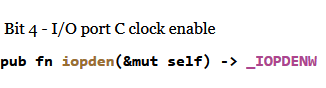
We find there that there should be a configuration bit named IOPCEN (IO - Port - C - Enable)
which enables port C clock.
The LEDs
The LEDs are physically connected to PC8 and PC9 ports over some resistors.
If there is a high I/O voltage on these pins, the corresponding LEDs should light up.
Flipping bits with Rust to light up the LEDs
We learned a few things:
- The
APB2clock for port C needs to be enabled to do anything with port C; - The port C has to be configured as Output;
- We can then flip some bits to send port C pins
8and9high, lighting up the LEDs connected to pinsPC8andPC9.
stm32f1 crate documentation
Let’s generate and open the docs for our device crate stm32f1:
cargo doc -p stm32f1 --open
Inside the documentation, we find stm32f1::stm32f100 submodule:
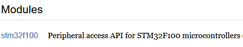
This API is generated with svd2rust tool, and
inside the svd2rust documentation
we can find hints of how to use this API.
Everything starts by getting access to Peripherals:
(main.rs, main function)
let peripherals = stm32f1::stm32f100::Peripherals::take().unwrap();

// continue here
From the Peripherals, we will need Reset and Clock Control, or RCC:
let rcc = peripherals.RCC;

// continue here
As well as GPIOC (GPIO C port):
let port_c = peripherals.GPIOC;

// continue here
When we browse the docs, we find that all peripheral types have a pointer
to corresponding RegisterBlock type. It refers to a number of registers grouped together.
For example, the stm32f1::stm32f100::RCC
type has a pointer to rcc::RegisterBlock (although the rcc:: is not reflected in
generated documentation):
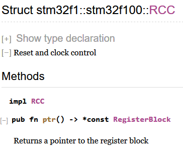
So to find the methods on RCC, we can drill down to rcc::RegisterBlock type. It contains
apb2enr individual register field that has the same name that was in the manual.
All the registers are used to write, modify, read, or reset the bits in them.
Inside the rcc::APB2ENR register type, we find methods to do just that:
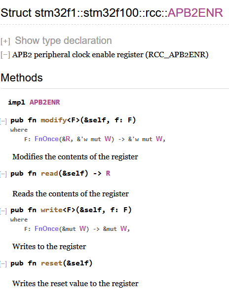
So, we can call write on rcc.apb2enr:
rcc.apb2enr.write(|w| ???);
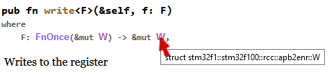
The write method expects a closure that does actual writing, and it gets this reference to
W type. It looks like a generic type, but it is not - we can click on it:
And inside a heap of methods, we find the method that gets us to the bit that can enable Port C clock:
And there we can call the bit(true)/set_bit() or bit(false)/clear_bit() functions
to set or unset the bit. Let’s do just that:
rcc.apb2enr.write(|w| w.iopcen().bit(true));

// continue here
Similarly, we get to Port C CRH register, and configure pins 8 and 9 to be
in MODE 01 (output) with CNF 00 (push-pull):
port_c.crh.write(|w| unsafe {
    w
        .mode8().bits(0b01)
        .cnf8().bits(0b00)
        .mode9().bits(0b01)
        .cnf9().bits(0b00)
});
There is a bit of unsafe code here, because the bits function can theoretically go out
of bounds and flip some bits that it should not have access to.
We can make previous code a bit nicer by introducing some constants:
const MODE_INPUT: u8 = 0b00;
const MODE_OUTPUT_10MHz: u8 = 0b01;
const MODE_OUTPUT_2MHz: u8 = 0b10;
const MODE_OUTPUT_50MHz: u8 = 0b11;

const CNF_OUTPUT_PUSHPULL: u8 = 0b00;
const CNF_INPUT_FLOATING: u8 = 0b01;

port_c.crh.write(|w| unsafe {
    w
        .mode8().bits(MODE_OUTPUT_10MHz)
        .cnf8().bits(CNF_OUTPUT_PUSHPULL)
        .mode9().bits(MODE_OUTPUT_10MHz)
        .cnf9().bits(CNF_OUTPUT_PUSHPULL)
});

// continue here
Finally, we use Port’s BSRR “Bit Set” register to flip bits 8 and 9 high:
port_c.bsrr.write(|w|
    w
        .bs8().set_bit()
        .bs9().set_bit()
);
Wait for it
(gdb) target remote :3333
Remote debugging using :3333
0x00000000 in ?? ()
(gdb) load
Loading section .vector_table, size 0x130 lma 0x8000000
Loading section .text, size 0x214 lma 0x8000130
Start address 0x8000130, load size 836
Transfer rate: 5 KB/sec, 418 bytes/write.
(gdb) continue
Continuing.
Bam!
Thoughts
It’s not hard to flip some bits once you know which ones. However, it is very easy to become overwhelmed by the number of things to keep in mind. Add to the mix that Rust is very new in embedded world, add to the mix that we may be new to this microcontroller, and the task becomes very daunting.
However, if we persist, we get to the end :)